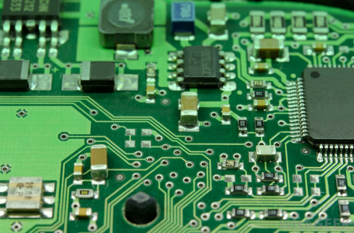
Printed circuit boards (PCBs) are the backbone of most electronics. These inventions pop up in all computational electronics, including devices like digital calculators and clocks. PCBs inform the electricity where to go, thus bringing your electronics to life. How PCB manufacturing process? Let’s find it out.
A How To On The PCB Manufacturing Process
Step 1: Design and output
Circuit boards must be compatible with a PCB layout made by the designer. Once the PCB design gets approval for production, the designer exports the design into a format the manufacturer supports. After a thorough examination, the designer forwards PCB files to PC board houses for production.
Step 2: From file to film
PCB printing starts once the designer outputs the PCB schematic files and the manufacturer carries out a DFM check. Manufacturers generally use a plotter to make photo films of the PCBs to print circuit boards. Manufacturers use these films to image the printed circuit boards.
Step 3: Printing inner layers
Where should the copper go? The creation of films aims to map out the copper path. Now, it’s time to print the path on the film onto a copper foil.
Step 4: Removing excess copper
The board moves onto unwanted copper removal. A powerful chemical preparation dissolves the excess copper. The process removes the exposed copper.
Step 5: Layer alignment
Now, the layers need alignment punches to make sure they all line up properly. The registration holes help to align the inner layers with the outer ones. A technician places the layers into the optical punch and the registration holes get punched accurately.
Step 6: Layer-up and bonding
Here, the circuit board takes its shape. All the separate layers wait for their union. They just need to fuse together. Also, outer layers should join with the substrate. The whole process takes place in two steps: layer-up and bonding.
Step 7: Drill
Finally, holes get bored into the stack board. All components such as copper-linking via holes and leaded aspects depend on the exactness of drill holes. These holes are usually drilled to 100 microns in diameter.
Step 8: Plating and copper deposition
After drilling, the panel proceeds to plating. The process essentially fuses the different layers. Chemical deposition comes in handy for fusing.
Step 9: Outer layer imaging
The panel’s outer layers need imaging with PCB design. The process begins with the layers in a sterile room to avoid contaminants from sticking to the layer’s surface. Then a layer of photo resist gets applied to the panel.
Step 10: Plating
Now, the PCB comes to the plating room. Here, the panel is electroplated. A thin layer of copper is used for the job.
Step 11: Final etching
The tin shields the copper during this stage. The undesirable exposed copper as well as the copper beneath the remaining resist layer is removed. The tin covers the valued copper throughout this process.
Step 12: Solder mask application
Here, the panels get cleaned and covered using the epoxy solder mask ink. Then, the boards receive a UV light blast, which subsequently passes through a photo film of solder mask. The process is finally followed by surface finish, silkscreen, electrical test, and profiling and V-scoring. If you go through all the steps, you don’t have to wonder – How PCB manufacturing process?
Looking for a pro to have PCB’s made? Look to Avanti Circuits today.


